How Does Sand Casting Work?
Sand casting works by generating a mold by forming a packed sand body around a wooden or rapid prototype master/pattern (or a part to be copied/reproduced). This mold requires features related to gas venting, fill and thermal compensation volumes, and core support, and it can then be filled with molten metal, which cools in place to faithfully reproduce the sand cavity.
What Is the Process of Sand Casting?
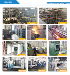
Sand casting is an intricate process of many small steps, each are simple and easily defined and not complex to master. However, all of these steps must be correctly executed to allow the possibility of a good-quality casting at the end of the process. Figure 1 below is a summary of the general process:
The general process is described below:
1. Position the Mold Pattern Within the Sand
The drag and cope are two open frames within which the cavity is formed. Together they make a casting box referred to as a flask. Place the drag (lower box) on a stable and robust work surface and place the pattern onto the work surface in the center of the drag, flat face down. Dust the pattern and the work surface with release powder such as talc to enable decoupling of the work surface and the pattern later. Cover the pattern and the inside of the drag with sand that has been riddled (shaken through a coarse sieve or riddler to remove clumps). Carefully ram this sand into the drag to form an integrated mass that closely fits the pattern. Complete the fill with sand and further ram this to integrate the whole. Be careful not to disturb the position of the half pattern, but ensure that the mass is well integrated. Use a strike bar to cut any bulge of sand from the face of the drag, to make a flat and smooth surface. Any stiff straight edge will suffice to cut this sand, but make sure the drag is filled with packed sand.
2. Establish the Gating System
With the drag filled, invert it to expose the upper face and the pattern. Decide where the conical feed and vent sprue positions should be placed. Trim a small receiver well and vent reservoir at each position, using a finisher tool (blunt knife or spoon). These features are small depressions that should be large enough for the sprue patterns to seat into. Cut channels from the receiver and vent wells to the faces of the pattern. This will allow the fill to flow from the wells to the cavity and the gas to escape as the second well fills. Liberally dust the entire drag surface with parting powder to allow the next stage to disengage when formed.
3. Position the Cope and Sprues and Complete the Fill
Place the cope onto the drag and position the sprue cones into the two wells you cut in the drag surface. Re-dust the surface with parting powder. Begin to riddle sand into the open top of the cope, making sure not to disturb the sprue patterns. Ram this new sand with care to not damage the drag setup but ensure that the sand is well integrated. Complete the fill of the cope and ram the sand, so that the fill forms an integrated and robust whole. Strike the upper face of the cope to produce a flat surface. When this is complete, remove the sprue patterns, being careful not to disturb the packed fill in the cope. Don’t worry about sand that falls into the hole, you can clear this later.
4. Extract the Mold Pattern
Carefully lift the cope off the drag and place it inverted next to the drag. Use a slick tool (precise repair and sand manipulation tool) to remove any upstanding features from the face of the cope fill. This is usually achieved by screwing one or more hooks into prepared holes in the flat surface of the pattern to lift it. More traditionally, draw spikes are hammered into the pattern to provide the lift “handle”. Where you cut the receiver/vent wells larger than the sprue patterns that were socketed into them, the space will have filled as you rammed the cope with fill. Cut away this excess and clean up any detritus by blowing it away. Without damaging the formed cavity, lift the pattern out of the cavity in the drag. Clean up any residues and make sure the feed channels are open and clear.
5. Vent the Cope, Reassemble the Flask, and Prepare for Fill
Using a vent rod, form small holes from the cavity to the topside of the cope. This will allow extra gas passages for venting when the cavity is filled. Make sure that the damage to the cavity is minimal. Vent the “high” points of the cavity. Try to avoid/minimize any cosmetic damage to the cavity face. Clean up any detritus by blowing it away. Clean up damaged edges of the sprue holes using a slick. Place the cope back onto the drag and lock the two halves together. Move the completed flask to the casting floor, ready to fill. Allow sufficient time (for green sand casts) for the moisture content to fall to an acceptable level. Other systems such as dry sand or furan-resin-bonded sand require less wait time.
6. Introduce Molten Metal Into the Mold Cavity
This description assumes melt has been completed and degassed. Poor degassing will result in a failed and porous casting. The crucible must be de-slagged and de-gassed completely, ready for the charge to be used to fill the cavity.
To complete this process, lift the crucible out of the furnace using crucible lift tongs. Place the crucible into the carrier tongs. Perform a final slag removal to make sure the surface of the melt is clean and smooth. Lift the crucible with the appropriate tongs that allow you to carry and tilt it with reliable precision. Carry the crucible to the flask and carefully commence the pour. Do not rush this stage; there will be steam and smoke, and a rushed pour will be less accurate, more hazardous, and more likely to erode the cavity faces and “include” sand detritus in the finished cast. Fill until the sprue holes are visibly full—this not only confirms fill but maintains some pressure to flow material into the cavity from these two cones, to compensate for initial shrinkage as the fill cools.
7. Allow Sufficient Time for the Metal To Cool
A rushed unpacking of the cast is hazardous and can result in distortion if the fill remains soft.
8. Crack Open the Mold To Extract the Metal Casting
Once cooled, unlock the cope from the drag and break out the casting and sand manually or using a shaker table. Sand is returned for re-use. Remove the casting features that are not part of the required component (sprue or feeder) by cutting with a saw or grinder. Fettle (clean up and improve) the finished part with a die-grinder or file to remove bumps from vent features, fill channels, and any sand that broke away from the cavity parts before casting.


