
The final tolerance on a casting part is influenced by many interconnected factors:
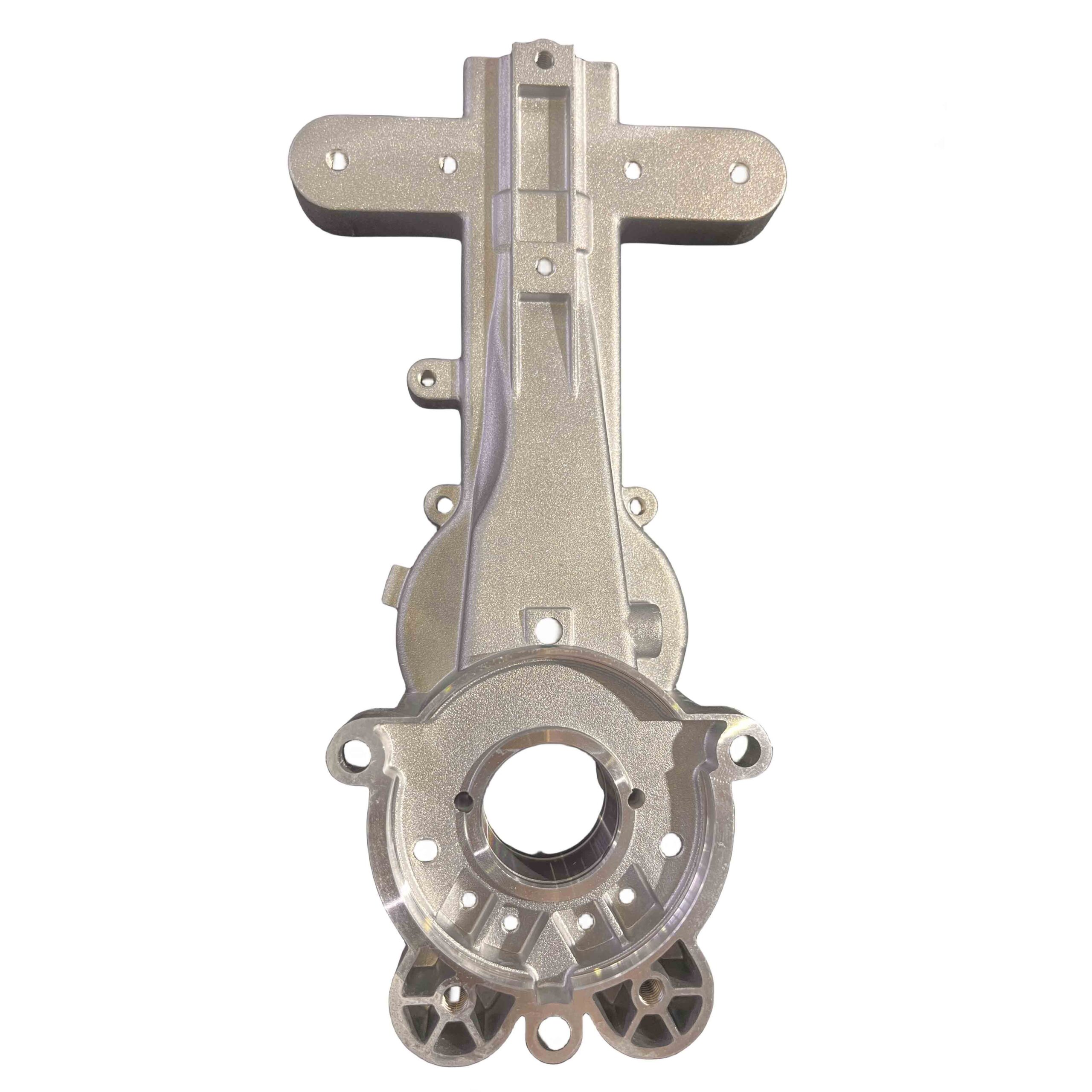
Part Geometry: Complex shapes with thin walls, internal cavities, or large flat surfaces are more challenging to hold to tight tolerances.
Pattern/Mold Quality: The precision and stability of the pattern and the sand mold itself are fundamental.
Metal Characteristics: Different alloys have varying solidification shrinkage rates, which must be accounted for in the pattern design.
Process Control: Factors like pouring temperature, sand compaction, and gating design significantly impact dimensional accuracy.
📝 Practical Guidance for Specification and Achievement
How to Specify on a Drawing: General tolerances are typically referenced in or near the title block of a drawing using a standard notation, for example: “ISO 8062-3-CT10“. For individual features requiring a different tolerance, a specific callout is used directly on the dimension.
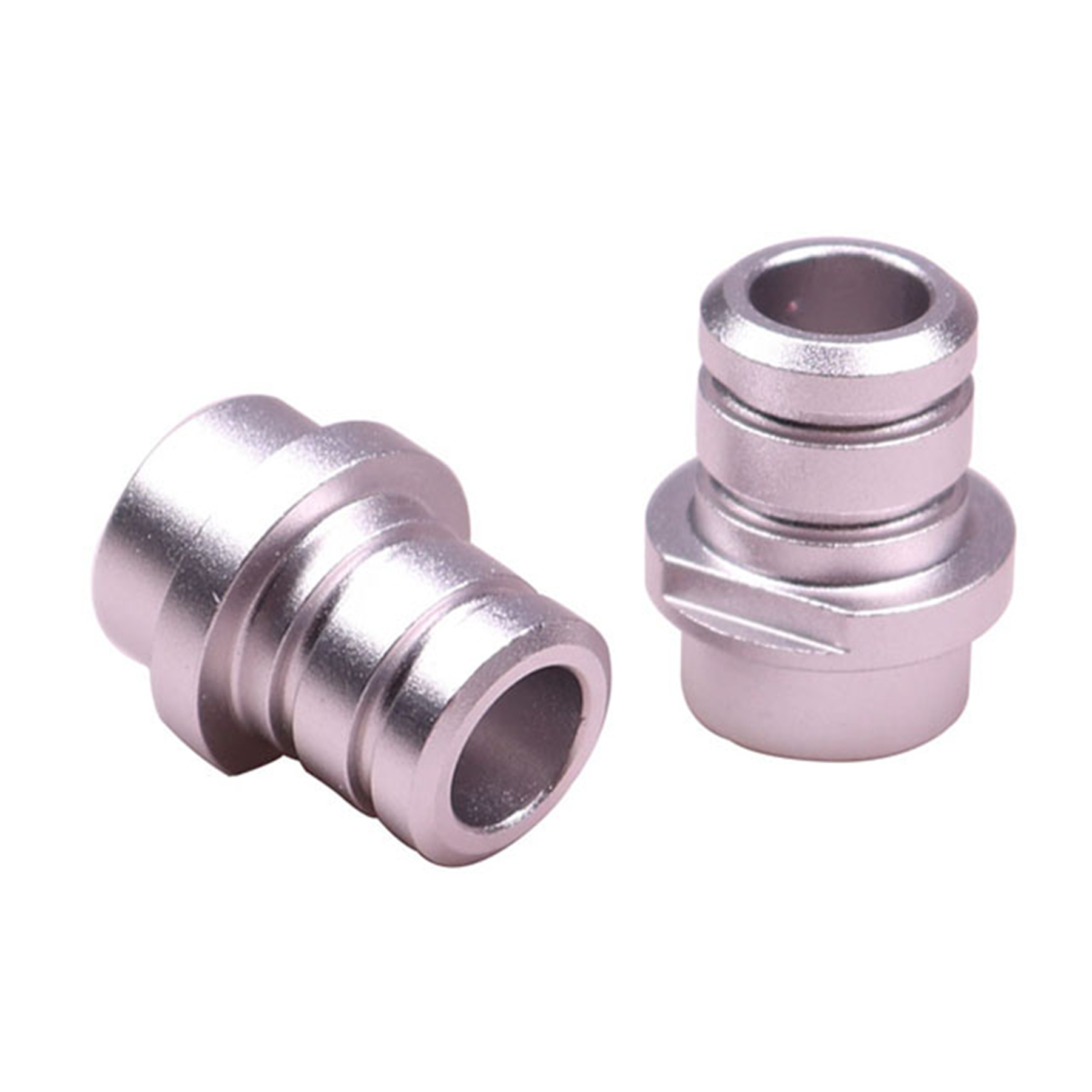
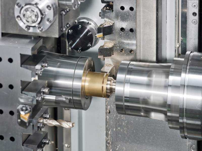
Achieving Tighter Tolerances: For critical dimensions, it is standard practice to designate machining allowances. The casting is produced with extra material, which is then removed by machining (e.g., turning, milling) to achieve a final dimension with a much tighter tolerance.
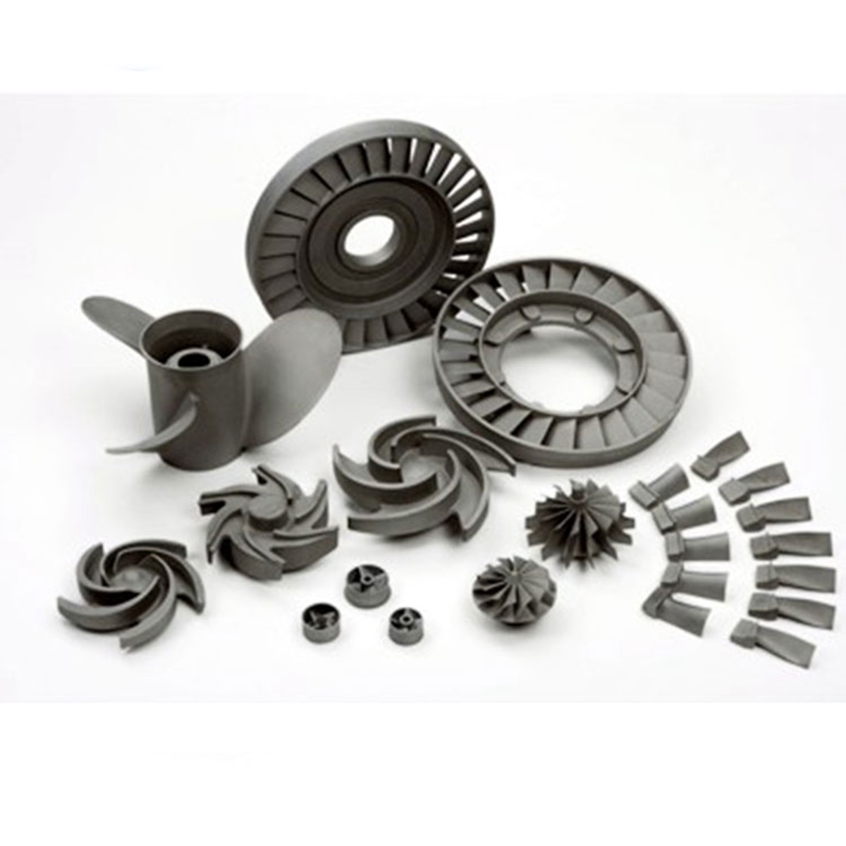
Real-World Example (Advanced Process): A research study using 3D sand printing and differential pressure casting for a thin-walled aluminum part reported a very tight dimensional tolerance range of -0.0976 mm to +0.1089 mm for its inner cavity, successfully meeting a design target of ±0.3 mm. Another study on thin-wall titanium castings achieved non-machined surface tolerances of ±0.2 mm. These examples are at the precision end of the spectrum.
In summary, the tolerance range for sand casting is determined by selecting an appropriate CT grade from relevant standards (like ISO 8062-3), which provides specific values based on part dimensions. Conventional sand casting typically operates in the CT8-CT12 range, while advanced methods can achieve much tighter control.