
Behind every precision component lies an invisible world of engineering that makes accuracy possible: tooling and fixturing. These unsung heroes of manufacturing—the molds that shape castings, the dies that form stampings, the fixtures that hold parts for machining—determine what can be produced, how accurately, and at what cost. At Juize Machinery, we design and fabricate much of our own tooling, giving us control over this critical foundation of quality. As a Gold Verified Supplier on Alibaba, we understand that exceptional components begin with exceptional tooling.
The Foundation of Precision
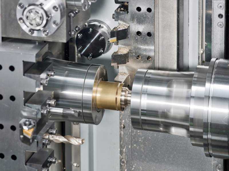
Consider a simple CNC machining operation. The cutting tool spins at thousands of revolutions per minute, removing material with each pass. But what holds the part? A fixture—custom-designed to locate the component precisely, clamp it securely, and provide access for cutting tools. Without proper fixturing, even the most capable machine cannot produce accurate parts.
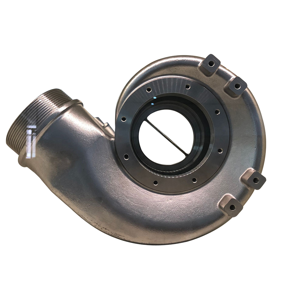
Consider a casting. The molten metal flows into a cavity formed by patterns and cores. The geometry of that cavity—every angle, every radius, every surface—comes from tooling. If the tooling is inaccurate, every casting from that tool will be inaccurate.
Tooling multiplies. A single pattern may produce thousands of castings. A stamping die may produce millions of parts. The precision of the tooling becomes the precision of every component it produces.
The Tooling Spectrum
Our capabilities span the full range of manufacturing tooling:
Patterns for Casting
Patterns create the impressions in sand molds that become castings. They must account for:
Draft Angles: Slight tapers that allow pattern removal without damaging molds.
Shrinkage Allowance: Compensation for metal contraction during cooling.
Machining Allowance: Extra material where subsequent machining will occur.
Parting Lines: The interfaces between mold halves, strategically placed for optimal geometry.
Patterns can be wood for prototypes and low volumes, aluminum or resin for medium production, or tool steel for high-volume automated lines. Each material offers different trade-offs in cost, durability, and precision.
Core Boxes
Internal cavities require cores—sand shapes placed within molds. Core boxes create these shapes, whether through:
Shell Core Process: Using heated core boxes and resin-coated sand to produce hollow, lightweight cores.
Hot Box Process: Heated core boxes with rapid-curing resin systems for high production rates.
Cold Box Process: Gas-cured resin systems operating at room temperature, offering dimensional precision.
Core box design determines core geometry, strength, and dimensional accuracy—directly affecting internal features of finished castings.
Dies for Forging
Forging dies shape metal under tremendous pressure. They must withstand repeated impact or compression while maintaining dimensional accuracy. Design considerations include:
Die Parting: Strategic location of the die separation line.
Flash Land: The gap where excess material escapes, creating flash that ensures complete die filling.
Draft Angles: Allowing forged part ejection.
Grain Flow: Die design influences how metal flows, affecting final mechanical properties.
Forging dies represent significant investment, but their precision directly translates to component strength and consistency.
Dies for Stamping
Stamping dies transform flat sheet metal into formed components through progressive operations. A progressive die may include dozens of stations:
Piercing Stations: Punch holes and openings.
Forming Stations: Bend and shape material.
Drawing Stations: Create cup-shaped forms.
Trimming Stations: Remove excess material.
Cutoff Stations: Separate completed parts from strip.
Each station must align perfectly with others, with clearances measured in thousandths of millimeters. Die design determines whether stamped parts fly through production or suffer from burrs, fractures, or dimensional variation.
Fixtures for Machining
Machining fixtures locate and secure components during cutting operations. Effective fixture design:
Establishes Datums: Reference features that relate part geometry to machine coordinates.
Provides Rigidity: Resists cutting forces without deflection.
Ensures Accessibility: Allows cutting tools to reach all required surfaces.
Facilitates Loading: Quick, repeatable part placement for production efficiency.
Manages Chips: Prevents swarf accumulation that could affect accuracy.
Modern fixtures often incorporate hydraulic or pneumatic clamping, automated positioning, and in-process sensing for high-volume production.
Gages and Inspection Tooling
Verifying conformance requires its own tooling:
Functional Gages: Go/no-go tools that simulate mating parts, verifying assembly compatibility.
Hard Gaging: Fixed measurement tools for rapid dimensional verification.
Inspection Fixtures: Devices that position parts for measurement on CMMs or optical systems.
Inspection tooling ensures that quality verification itself is accurate and repeatable.
The Design Intelligence Behind Tooling
Effective tooling requires deep understanding of both the manufacturing process and the final component’s function:
Process Knowledge
Different processes impose different requirements:
Casting Tooling: Must account for metal flow, solidification patterns, and thermal contraction.
Forging Dies: Must withstand extreme pressures and thermal cycling while maintaining geometry.
Stamping Tooling: Must manage material springback, stretching limits, and lubrication requirements.
Machining Fixtures: Must resist cutting forces while maintaining precise location.
Our tooling engineers understand these process demands intimately, designing tools that work with processes rather than against them.
Material Science
Tool materials must withstand their operating conditions:
Tool Steels: Various grades offer different combinations of hardness, toughness, and wear resistance.
Carbides: Extreme hardness for high-wear applications.
Ceramics: Heat resistance for high-temperature operations.
Copper Alloys: High thermal conductivity for cooling applications.
Polymers and Composites: Lightweight options for prototypes and low volumes.
Selecting the right tool material extends tool life, maintains precision, and controls costs.
Geometric Reasoning
Tooling designers translate component geometry into manufacturing geometry. A hole in the final part becomes a core pin in a die, a drilled feature in machining, or a pierced opening in stamping. Each transformation requires geometric reasoning that considers:
Draft requirements for ejection
Radii for stress reduction
Clearance for tool movement
Taper for proper fill
The Economics of Tooling
Tooling decisions involve significant economic trade-offs:
Initial Investment vs. Per-Part Cost
Higher-quality tooling costs more initially but produces parts faster, with less variation, and over longer production runs. The breakeven analysis depends on expected production volume.
Tool Life and Maintenance
All tooling wears. Harder tool materials last longer but cost more and may be harder to repair. Predictive maintenance programs track tool wear and schedule refurbishment before quality degrades.
Lead Time Considerations
Complex tooling requires weeks or months to design and fabricate. For urgent projects, we balance speed against durability—sometimes producing temporary tooling for initial production while permanent tooling progresses.
Design Iteration Costs
Design changes after tooling fabrication can be expensive. Our engineering collaboration minimizes this risk by thoroughly reviewing designs before tooling commitment.
In-House Tooling: The Juize Advantage
Unlike many manufacturers who outsource tooling, we maintain comprehensive in-house tool design and fabrication capabilities. This integration offers distinct advantages:
Rapid Iteration
When design adjustments prove necessary, we implement them immediately—no waiting for external tool shops, no shipping delays, no communication gaps.
Process-Integrated Design
Our tooling engineers work alongside production engineers. A challenge observed on the shop floor becomes tooling modification the same day. This feedback loop continuously improves both tooling and processes.
Quality Ownership
Tooling quality directly affects component quality. By controlling tooling fabrication, we control this fundamental quality driver completely.
Proprietary Knowledge
Tooling often embodies process expertise that distinguishes exceptional manufacturing. Keeping tooling development in-house protects this intellectual property.
Prototype to Production: The Tooling Journey
Tooling evolves through product lifecycles:
Prototype Tooling
For initial validation, we often produce simplified tooling—soft tools from aluminum or urethane, 3D-printed patterns, or single-cavity prototypes. These tools prove designs and produce samples for testing, at lower cost and shorter lead time than production tooling.
Bridge Tooling
As volumes increase, we may produce intermediate tooling—durable enough for initial production runs but not optimized for maximum volume. Bridge tooling allows market entry while permanent tooling completes.
Production Tooling
For full-scale production, we fabricate hardened tooling designed for millions of cycles, with cooling channels, automated ejection, and all features for maximum efficiency.
Replacement and Refurbishment
When production tooling wears, we refurbish or replace it to original specifications, ensuring consistency throughout product life.
Tooling as Intellectual Property
Well-designed tooling embodies manufacturing knowledge that competitors cannot easily replicate. For many clients, tooling represents valuable intellectual property that must be protected. Our practices include:
Secure tooling storage and handling
Controlled access to tooling designs
Clear agreements on tooling ownership
Documentation retention for future reference
When clients own their tooling, we maintain it respectfully and release it upon request. When we develop tooling for clients, we clarify ownership terms before beginning.
Designing for Tooling
Optimal components consider tooling during design. Our engineering team advises clients on:
Draft Angles: Appropriate tapers for pattern or die ejection.
Uniform Wall Sections: Promoting consistent filling and cooling.
Radii and Fillets: Reducing stress concentrations and improving material flow.
Parting Line Placement: Strategic location of mold or die separation.
Undercut Management: Features requiring side-actions or collapsible cores.
These design-for-tooling considerations improve manufacturability, reduce costs, and enhance quality—without compromising component function.
Exploring how optimized tooling might benefit your next project?
Let our tooling engineers collaborate with you. From initial design consultation through production implementation, we ensure your components rest on the strongest possible foundation.