In the world of mechanical engineering and precision manufacturing, an Interference Fit (also known as a Press Fit or Friction Fit) is a crucial type of connection between two components. It is a fundamental concept for creating strong, permanent, and precise assemblies without the need for fasteners or adhesives.
The Core Principle: More Hole, Less Shaft
At its simplest, an interference fit is defined by a specific dimensional relationship:
The shaft (or male component) is deliberately manufactured to be slightly larger than the hole (or female component).
During assembly, force is applied to press the shaft into the hole.
Once assembled, the elastic and plastic deformation of the materials creates a powerful, permanent joint.
This intentional mismatch in sizes is the “interference.”
Key Terminology:
Negative Clearance: This is the technical term for the “interference.” While a standard fit has a positive clearance (space between the parts), an interference fit has a negative clearance.
Press Fit: Refers to the assembly method—using a press to force the parts together.
Shrink Fit / Expansion Fit: Alternative assembly methods using heat/cold to temporarily alter the part sizes.
How It Works: The Science Behind the Strength
The strength of an interference fit comes from three key factors:
Radial Pressure: The oversized shaft compresses the material of the hole inward, while the hole stretches the shaft material outward. This creates a constant, uniform pressure at the interface between the two parts.
Static Friction: The high radial pressure results in a tremendous amount of static friction. This friction is what resists:
Torque Transmission: Prevents gears, pulleys, and bearings from spinning on a shaft.
Axial Load: Prevents components from sliding apart along the axis of the shaft.
Material Elasticity: Most engineering materials (like steel, aluminum) are elastic to a degree. They act like very stiff springs, constantly pushing back against the deformation, which maintains the pressure and friction indefinitely.
Common Methods of Assembly
You cannot simply hammer parts together with a large interference; it could damage them. The chosen method depends on the level of interference and the part sizes.
Force Pressing: Using a hydraulic or arbor press to push the shaft into the hole. This is the most common method for small to medium interferences.
Shrink Fitting:
How: The hole component (e.g., a gear) is heated, causing it to expand. The shaft component is kept at room temperature. The expanded hole easily slides onto the shaft. As the assembly cools, the hole contracts, creating the interference fit.
Use Case: For large interferences or large, heavy components where pressing force would be impractical.
Expansion Fitting (or Cold Fitting):
How: The shaft component is cooled (e.g., with dry ice or liquid nitrogen), causing it to contract. It is then inserted into the room-temperature hole. As the shaft warms up, it expands, creating the interference fit.
Use Case: Often used for delicate parts that might be damaged by heat, or when heating the outer component is not feasible.
Advantages and Disadvantages
Advantages:
High Strength & Rigidity: Creates a joint that is often stronger than the individual parts.
Excellent Torque Transmission: Ideal for power transmission components like gears and couplings.
No Stress Concentors: Unlike keys or splines, there are no grooves or notches that create weak points prone to fatigue failure.
Simplified Design: Reduces or eliminates the need for additional fasteners like screws, keys, pins, and adhesives.
Maintenance-Free: Once assembled, it requires no further tightening or adjustment.
Excellent Dimensional Accuracy & Concentricity: Provides a perfectly centered assembly.
Disadvantages:
Permanent Assembly: Disassembly is very difficult and often destroys the components.
High Stresses: The interference creates internal stresses in the parts, which must be considered in the design to avoid yield or fracture.
Precise Machining Required: Requires very tight tolerances and excellent surface finishes, which can increase cost.
Specialized Assembly Equipment: Often requires presses, ovens, or cryogenic facilities.
Real-World Applications
Interference fits are everywhere in machinery:
Bearings on Shafts / Housings: The most common application. The bearing inner ring is pressed onto a shaft, and the outer ring is pressed into a housing.
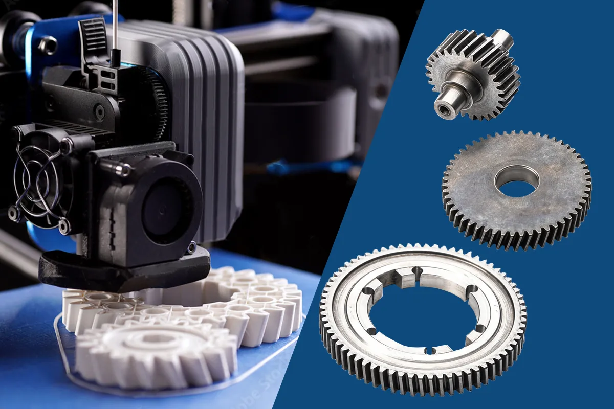
Gears and Pulleys: Mounted onto shafts to transmit power without keys.
Wheels on Axles: Such as railway wheels on axles (a classic shrink fit example).
Cutting Tools on Tool Holders: In machining centers.
Precision Medical Devices: For assembling components that must be sterile and free of crevices.
Design Considerations
Designing a successful interference fit is a precise science. Engineers must calculate:
Amount of Interference: The difference in diameters. This is the most critical variable.
Material Properties: The yield strength, Young’s modulus (stiffness), and Poisson’s ratio of both materials.
Coefficient of Friction: Between the two materials.
Part Geometry: The diameter and the thickness of the outer ring (hub). A very thin hub can deform too much or even crack.
In conclusion, an interference fit is a powerful, elegant, and highly reliable method of joining components. It leverages the fundamental properties of materials to create assemblies that are strong, precise, and integral to the function of countless machines and devices we rely on every day.


